
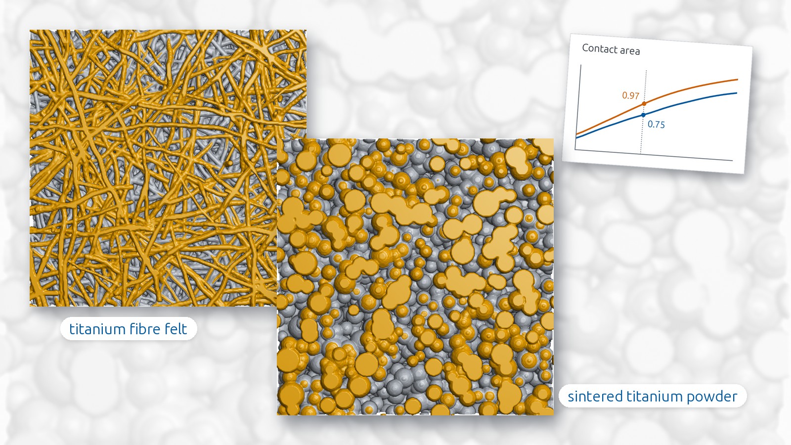
Titanium fibre felt and sintered titanium powder are the two common designs of the porous transport layer (PTL) in a PEM water electrolyser. Two virtual layers, one of each design, are compared here and set against published cell data to find which of their differences can matter in a cell. Those are the differences at the contact with the catalyst layer, where the powder has the larger contact area.
The PTL lies between the anode catalyst layer and the flow field. Water reaches the catalyst through its pores and the oxygen formed there leaves through the same pores, while the current runs through the titanium and enters the catalyst layer where the two touch. Pore space and titanium share one volume, and porosity, fibre or particle size and thickness are set as a compromise between them.
PTL designs are compared in cells. A cell is built with each candidate, and the polarisation curve and impedance spectroscopy split its losses into kinetic, ohmic and mass transport parts; each candidate needs a sample, an assembly and a test run, and the result is that of the whole assembly. Rigs for the layer alone, such as mercury intrusion, permeability and conductivity measurements, give one property each under the conditions of the rig. Water and gas inside an operating cell are imaged by neutron radiography at neutron sources and by X-ray tomography at synchrotrons, large research facilities where beam time is applied for.
A laboratory µCT resolves the fibres and particles of a titanium PTL in a few hours, and titanium and pore separate cleanly in such a scan. On a scan like that, or on a structure generated from design data before a sample exists, pore sizes, permeability and conductivity in each direction, the contact with the catalyst layer and the gas breakthrough are computed on one and the same structure on a workstation. The two layers compared here were generated and analysed in GeoDict.
Two virtual PTLs
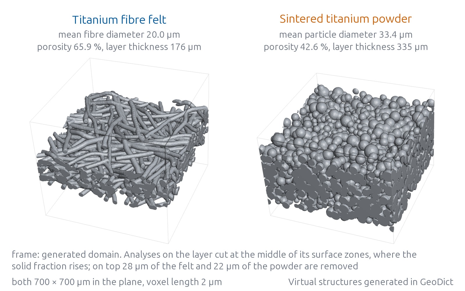
The felt was generated with curved fibres that lie almost entirely in the plane of the layer, the powder as a packing of spherical particles joined at their contacts by a sintering step. Fibre diameter, particle size, porosity and thickness of both layers lie within the published values for their design; the porosity of the powder lies in the upper part of the values published for sintered titanium layers. Each layer was generated with typical values of its own design, and the two were not matched to each other, so they differ in porosity and thickness as well as in design; the felt is the more open and the thinner of the two. The thickness of each layer follows from the generation settings. Both structures have the same size in the plane and the same resolution. Pore analyses and simulations run on the layer cut at the middle of its surface zone at top and bottom, the zone in which the solid fraction rises from zero to that of the interior, so the outermost fibres and particles are removed and every analysis starts on a flat cut.
Pore space, water flow and conduction
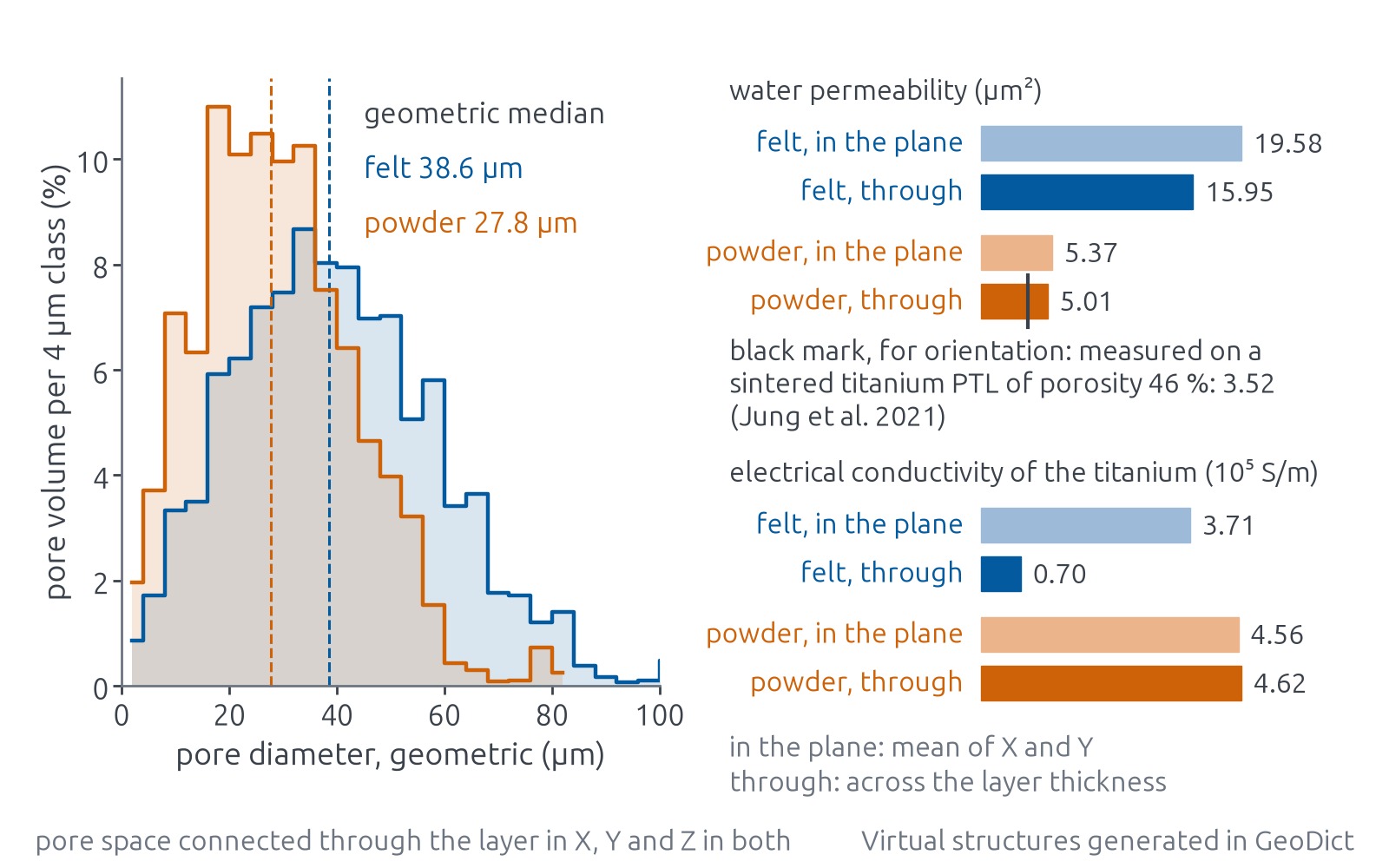
The felt has the wider pores, and in both layers the pore space is connected through the layer in all three directions. These pore sizes are geometric, from spheres fitted throughout the pore space.
In a Stokes flow simulation the water permeability of the felt is higher than that of the powder in every direction, by about the same factor through the thickness as in the plane. One published measurement serves for orientation. It was taken on a sintered titanium PTL that is more porous than the powder here, and that layer is somewhat less permeable through its thickness than computed for the powder. Porosity does not explain this direction. The particle size and the sintering of that sample, which set the width of the necks between particles, are not known here. Electrical conduction in the titanium shows the opposite ranking. Because its fibres lie flat, the felt conducts far better in the plane than across the layer. The powder conducts about equally in all directions, and across the layer it conducts much better than the felt.
Contact with the catalyst layer
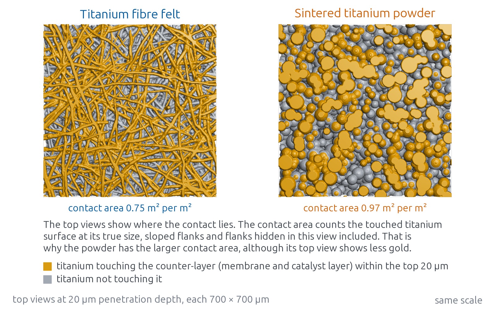
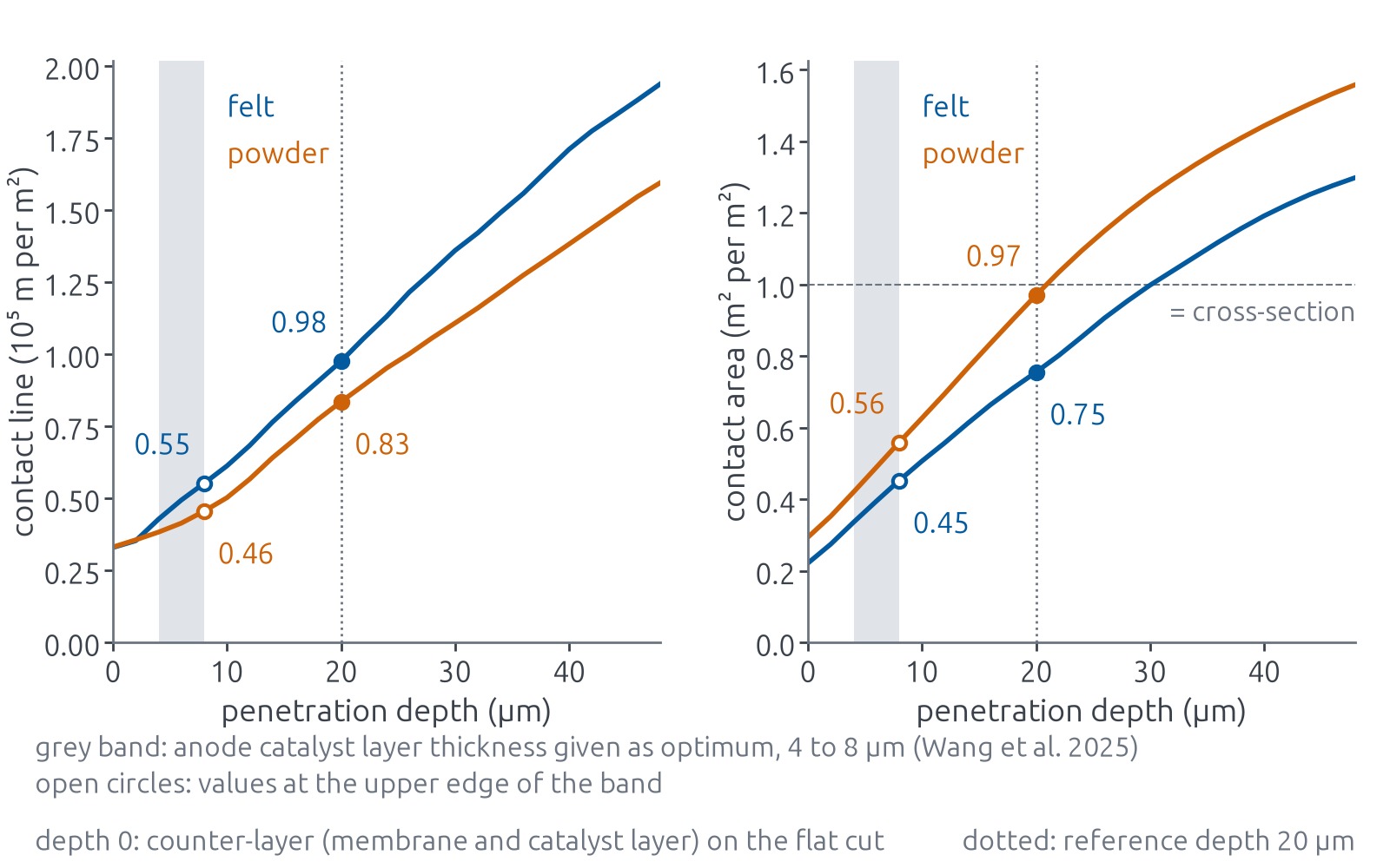
When the cell is clamped, membrane and catalyst layer are pressed into the rough top face of the PTL. In the analysis a counter-layer, which stands for membrane and catalyst layer together, is advanced into the top face in steps of one voxel, and at each step the pore space reachable from above is filled with it. The penetration depth is the distance it has advanced. Two quantities are measured at each step. The contact area between titanium and counter-layer is where the current crosses the interface, and it sets the contact resistance. The contact line is the line where titanium, counter-layer and pore meet; it measures how finely the contact is divided, independent of how much contact there is.
The powder has the larger contact area over the whole computed range of depths. The felt has the longer contact line from a few micrometres of penetration on; at the shallowest steps the two are level. Both rankings are the same at the thickness of an anode catalyst layer and at a reference depth set for the comparison, which lies deeper because the counter-layer stands for membrane and catalyst layer together. In the felt the contact lies along long fibre strands, each with contact line along its whole length. In the powder it lies on fewer, larger patches, among them the flat faces where the cut runs through particles. The contact area counts every titanium face the counter-layer touches at its true size, including sloped flanks and flanks hidden from above, so it can exceed the cross-section of the sample, and it starts above zero because at the first step the counter-layer already rests on the flat cut faces.
The powder holds much more titanium per volume than the felt, and part of its larger contact area follows from that; in proportion, its lead in contact area is smaller than its lead in titanium. How much of the lead comes from the titanium content and how much from the particle shape was not separated, since that would take a powder generated at the porosity of the felt. The flat cut faces give the powder a lead from the first step on, before the counter-layer enters any pore, and the larger part of its lead at the reference depth builds up below the cut.
Gas breakthrough
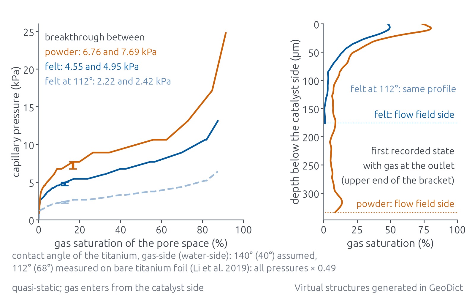
The oxygen formed at the catalyst has to push water out of the pores on its way to the flow field. In the capillary pressure simulation gas enters from the catalyst side, and at each pressure step it fills the pores it can reach through throats wide enough for that pressure. Breakthrough is the first state with a connected gas path across the layer. GeoDict records the gas distribution only at some of the steps, so the breakthrough pressure is known as a range between two recorded steps. The felt breaks through at a lower pressure than the powder, in line with its wider pores. In the first recorded state with gas at the outlet, the gas saturation in both layers is highest near the catalyst side. In the felt it falls to very little towards the flow field side; in the powder a larger share of the gas lies deeper, at a low level through the rest of the thickness.
The simulation uses one contact angle for all titanium surfaces, an assumed example value. Each angle is given twice, measured through the gas and measured through the water, the second being the one a contact angle measurement in the laboratory reports. With one uniform angle every capillary pressure scales with the cosine of the angle and the gas distribution stays the same. A run of the felt with the angle measured on bare titanium foil gives the same gas distribution at proportionally lower pressures. Measured angles on titanium span a wide range, and the pressure scale moves with them; the ranking of the two layers holds for any angle that is the same on both.
Use in development
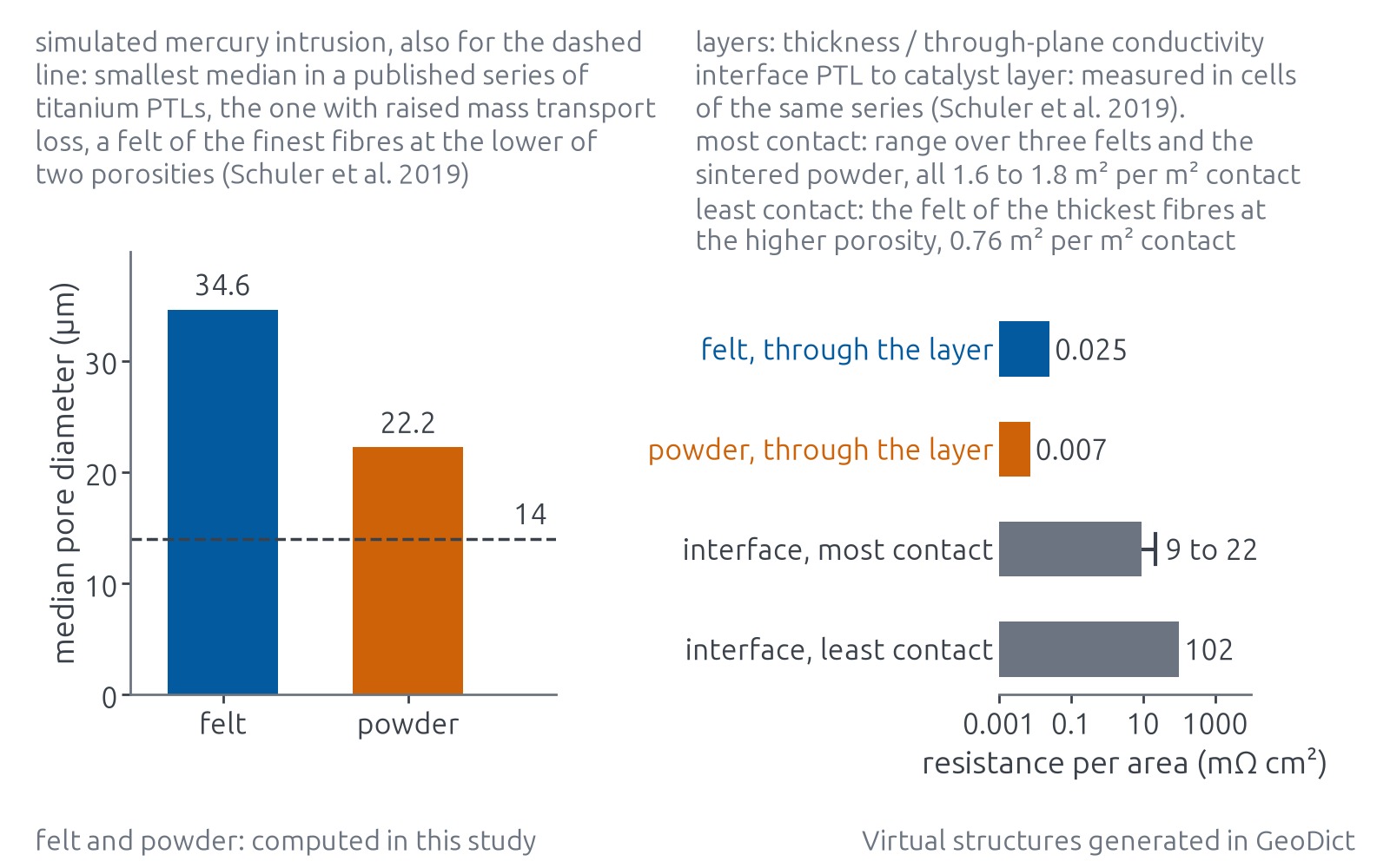
Set against published cell data, the computed differences do not weigh equally, and for layers like these two some of them are not worth a cell test. The resistance of each layer across its thickness, from thickness and through-plane conductivity, is far below the contact resistance between PTL and catalyst layer measured in cells with titanium PTLs. A difference in through-plane conduction, even one as large as that between felt and powder, therefore hardly shows at cell level.
The same holds for permeability above a pore size threshold. In a published series of six titanium fibre felts, at two porosities on either side of that of the felt here, and one sintered powder as reference, permeability and diffusivity showed no measurable correlation with performance as long as the pores were wide enough. The pore size in that series comes from simulated mercury intrusion, which lets spheres advance from one surface only through openings wide enough to pass, so a wide pore behind a narrow neck counts at the size of the neck, and its median is smaller than the geometric one. The one material with raised mass transport loss, the felt of the finest fibres at the lower porosity, had the finest pores of the series, and by the same measure both layers here have clearly wider pores. As long as the finding of the series holds, a permeability difference between layers in this range is not worth a cell test either.
In the same series cell performance correlated with the contact area to the catalyst layer, and the share of the catalyst taking part in the reaction moved with it, so for layers like these the test effort is better spent at the interface. The series held only one sintered powder. If its finding holds for sintered powders as well, the larger contact area of the powder is the difference between these two layers that can count in a cell. The felt has the longer contact line, which measures how finely the contact is divided; its effect in a cell is not established.
A fine layer facing the catalyst on a coarse support, a felt with finer fibres at the surface, or a powder with smaller particles or a lower porosity at the top face can each be generated and computed before it is made. In published computations on generated sintered powders, full contact was reached at a shallower depth with smaller particles and with a lower porosity, and a fine layer facing the catalyst has been reported to improve catalyst utilisation in cells. For each variant the same analysis gives contact area and contact line over the penetration depth, the intrusion median against the published threshold and the gas breakthrough. A variant that gains contact but narrows its pores towards the threshold is then recognised before a sample is built, and the cell test starts from fewer candidates.
Limits
Both structures are virtual, generated with published parameters and with assumptions where the literature gives none. No scan of a PTL was analysed. No result of this study has been validated against a measurement; one published permeability is shown for orientation. The literature gathered for this study holds no comparable measurement of the two-phase results and no cell data on gas breakthrough. The two layers differ in porosity and thickness as well as in design, so the comparison does not separate the effect of fibres from that of particles.
The electrical conductivity is that of a bare titanium skeleton, without oxide layers, coatings or contact resistance to the flow field. Compression of the layer in the stack is not included.
Each layer is cut at the middle of its surface zone, which removes the outermost fibres and particles. The contact values therefore describe the cut face; the as-made surface was not analysed. The interface analysis is geometric. It contains no mechanics, no proton path to the membrane and no conduction within the catalyst layer, so it does not give the share of catalyst along the contact line that takes part in the reaction. The depth that membrane and catalyst layer reach in a cell depends on clamping pressure and membrane, which are not modelled, and the reference depth is a chosen value.
The two-phase simulation is quasi-static. It gives the gas distribution in equilibrium at each pressure and nothing about the motion or detachment of bubbles. Its pressures scale with the assumed contact angle. The effect of the gas distribution on the water supply of the catalyst layer is outside the analysis.
The published series that relates contact area to cell performance consisted mainly of felts, and with a single sintered powder as reference, so its finding is not established for sintered powders. Absolute values for a product need a scan of it and a measurement to compare against.
Made with the GeoDict Copilot
This study was made with the GeoDict Copilot, the AI agent that cvt engineering develops for GeoDict.
Analysis of porous transport layers
cvt engineering offers these analyses for PTLs and other porous layers of electrolysers and fuel cells. The input is a µCT or nanoCT scan of a sample that resolves its fibres or particles, or design data from which a structure is generated. The result for the sample or design is the set of pore sizes, permeability and conductivity per direction, contact area and contact line over the penetration depth, and capillary pressure with breakthrough, with computed variants beside it.